
The relevant input for the design is defined in the Seismic Configuration. Afterwards, a new Seismic Configuration can be defined by entering a descriptive configuration name, and then selecting the applicable SFRS frame type and member type.
- Full integration in RFEM/RSTAB with import of relevant internal forces
- Design checks for the elastic-elastic and elastic-plastic methods
- Graphical selection of members and sets of members for design
- Analysis for several load and design cases
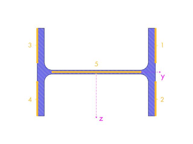
- Design based on the buckling field parameters integrated in the cross-section library for the cross-section parts supported on one and both sides
- Optional determination of shear stresses according to comment on El. (745)
- Possibility to consider the weld thickness in the design of welded cross-sections, which has the effect of a shortening of the cross-section part width
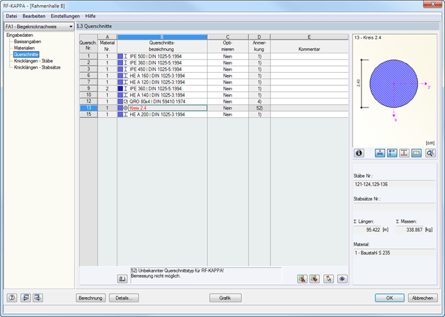
- Cross-section optimization with the option to export modified cross-sections

Lines can be imported into RFEM either as lines or members. The names of layers are adopted as the cross-section names, and the first material from the predefined materials is assigned. However, if the section of the Dlubal cross-section library and the material are recognized from the layer name, they are adopted as well.

The seismic design result is categorized into two sections: member requirements and connection requirements.
The "Seismic Requirements" include the Required Flexural Strength and the Required Shear Strength of the beam-to-column connection for moment frames. They are listed in the ‘Moment Frame Connection by Member’ tab. For braced frames, the Required Connection Tensile Strength and the Required Connection Compressive Strength of the brace are listed in the ‘Brace Connection by Member’ tab.
The program provides the performed design checks in tables. The design check details clearly display the formulas and references to the standard.
- Full integration in RFEM/RSTAB including import of all relevant internal forces
- Intelligent presetting of flexural buckling-specific design parameters
- Automatic determination of the distribution of internal forces and classification according to DIN 18800, Part 2
- Optional import of buckling lengths from the RF-STABILITY/RSBUCK add-on module. For this, a comfortable graphical selection of the relevant buckling mode is possible
- Optimizing Cross-Sections
- Optional calculation according to both design methods of DIN 18800, Part 2
- Automatic determination of the most unfavorable design location, also for tapered members
- Check of c/t-limit values according to DIN 18800, Part 1
- Design of any thin-walled RFEM/RSTAB or SHAPE-THIN section for compression and bending without interaction according to the elastic-plastic method
- Design of I-shaped rolled and welded sections, I-like sections, box sections, and pipes subjected to bending and compression with iteration according to the elastic-plastic method
- Clearly arranged, comprehensible design checks with all intermediate values in the short and long forms
- Parts list of members and sets of members
- Direct export of all results to MS Excel
- A manual with manually calculated examples
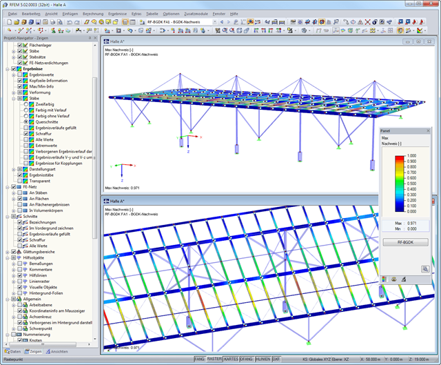
After the design, the results are displayed in different windows sorted by cross-sections, members, sets of members, or x-locations. The corresponding cross-section graphic is always displayed with the result values in tables. In RFEM/RSTAB, they are highlighted by different colors in the structural model. Critical or oversized components can be identified at a glance. You can modify the colors and values assigned.
Result diagrams of a member or a set of members ensure targeted evaluation. It is also possible to represent all intermediate values.
The masses determined during the design are displayed in parts lists for both members and sets of members.
Furthermore, you can export all result tables to MS Excel or in a CSV file. A special transfer menu defines all specifications required for the export.
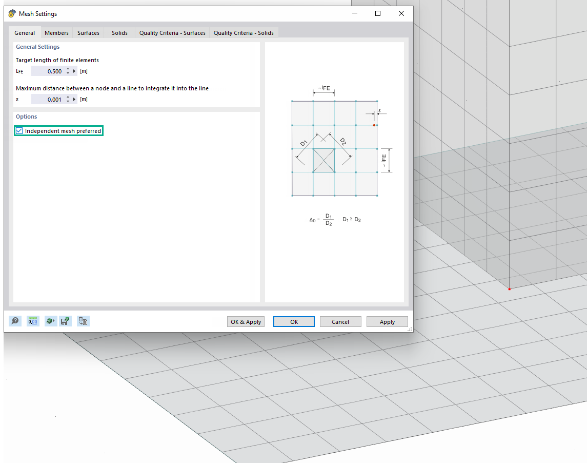
Use the "Independent mesh preferred" option in the FE mesh settings to create an independent FE mesh for the integrated objects. This allows you to generate a significantly more detailed and precise FE mesh for individual objects that are integrated into one another.

- Design of five types of seismic force-resisting systems (SFRS) includes Special Moment Frame (SMF), Intermediate Moment Frame (IMF), Ordinary Moment Frame (OMF), Ordinary Concentrically Braced Frame (OCBF), and Special Concentrically Braced Frame (SCBF)
- Ductility check of the width-to thickness ratios for webs and flanges
- Calculation of the required strength and stiffness for stability bracing of beams
- Calculation of the maximum spacing for stability bracing of beams
- Calculation of the required strength at hinge locations for stability bracing of beams
- Calculation of the column required strength with the option to neglect all bending moments, shear, and torsion for overstrength limit state
- Design check of column and brace slenderness ratios


In the Modal Analysis add-on, you have the option to automatically increase the sought eigenvalues until reaching a defined effective modal mass factor. All translational directions activated as masses for the modal analysis are taken into account.
Thus, it is possible to easily calculate the required 90% of the effective modal mass for the response spectrum method.